
Setup and Operation
Mounting, configuration and suspension settings
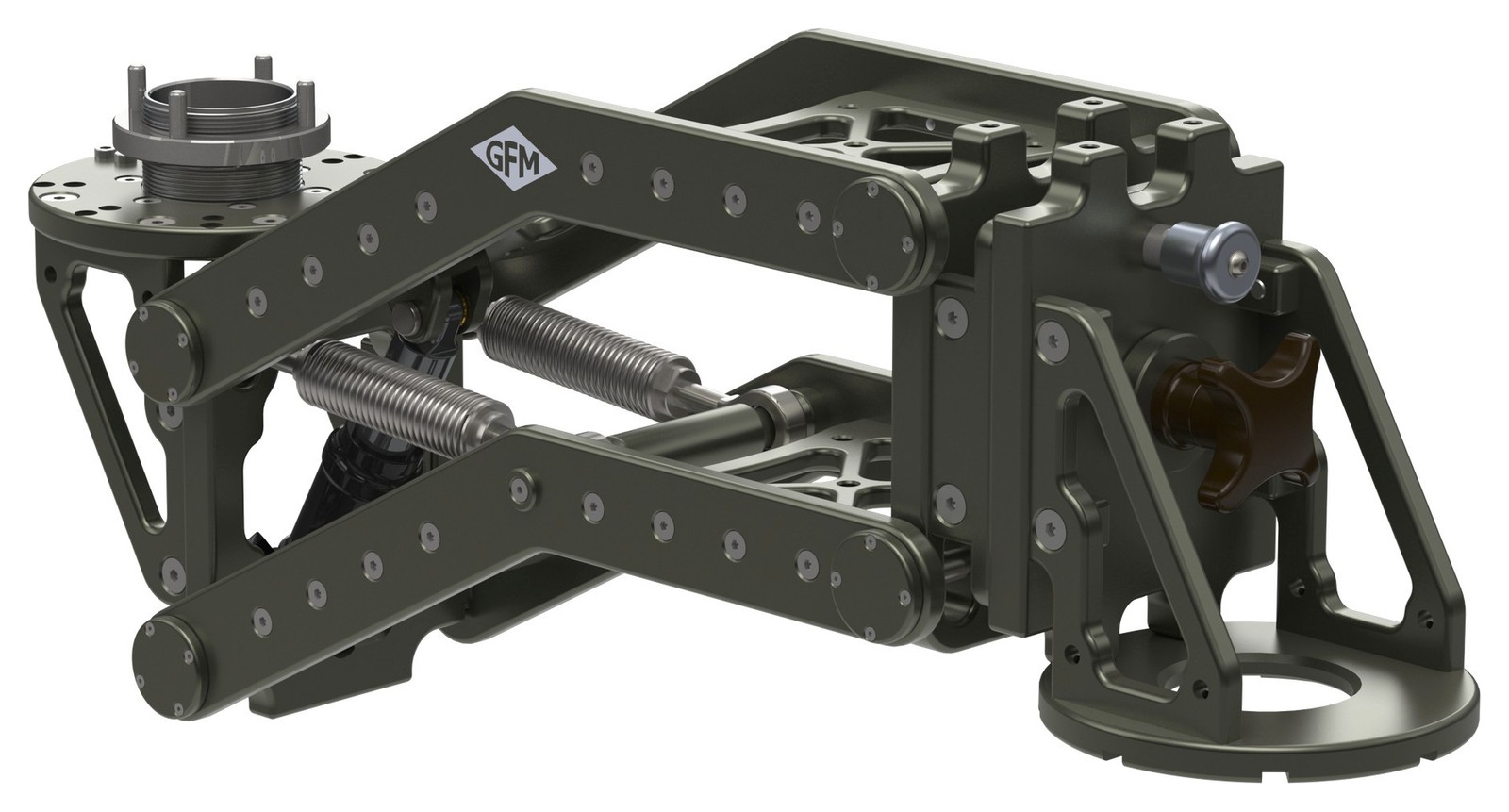
The GF-Mini Shock Absorber sits between the mount and a gyro-stabilized head. It takes out high and low frequency vibration and the hard knocks of a fast car or crane move. It connects to Mitchell or to 48 mm scaffold tube, carries 10 to 65 kg and has 16 cm of lift range. Weight 9.8 kg, size 38 × 19 × 34 cm, working temperature −20 to +50 °C.
Mount it on a Mitchell
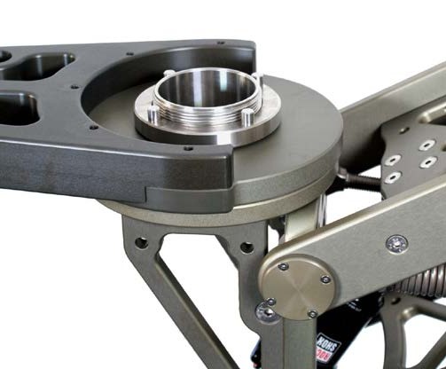
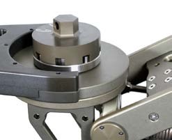
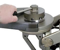
Push the Mitchell threaded shaft into the Mitchell mount on the car or crane. Turn the castle nut clockwise by hand, then lock it tight with the locking tool and the lever.
Or mount it on scaffold tube
Where there is no Mitchell, the scaffold double mount from the set clamps the shock absorber to 48 mm scaffold tube. Close all four clamps and tighten the levers before you put any load on it.
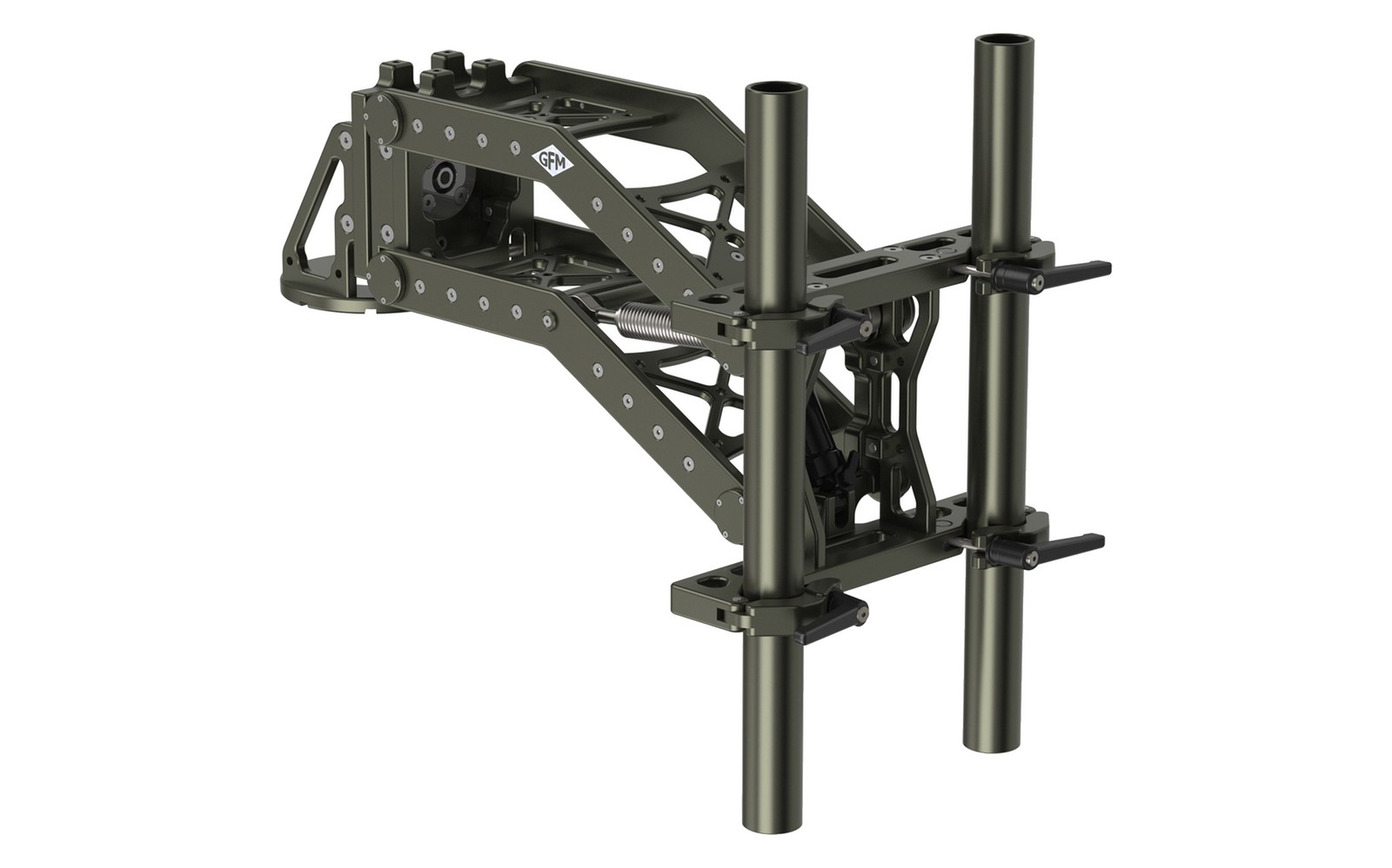
The nose mount
The nose carries a standard Mitchell mount for the GF-Iso Dampener or the head. Earlier versions also offered a 150 mm bowl insert for the nose. It has been discontinued and is no longer available.
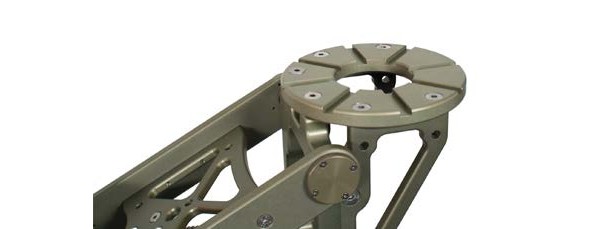
Choose a configuration
Rear and front can each be set underslung or overslung, which gives four standard configurations. 1: rear underslung, front underslung. 2: rear underslung, front overslung. 3: rear overslung, front underslung. 4: rear overslung, front overslung.
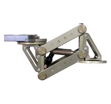
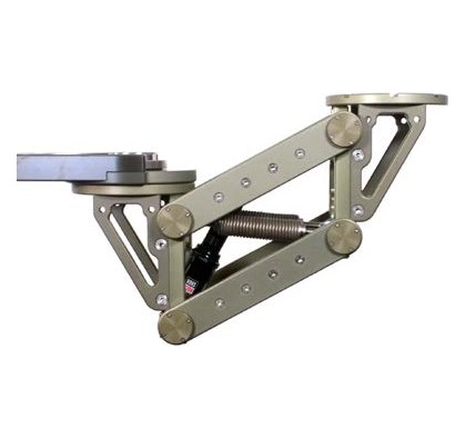
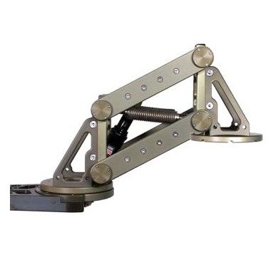
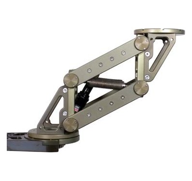
Switch between over- and underslung
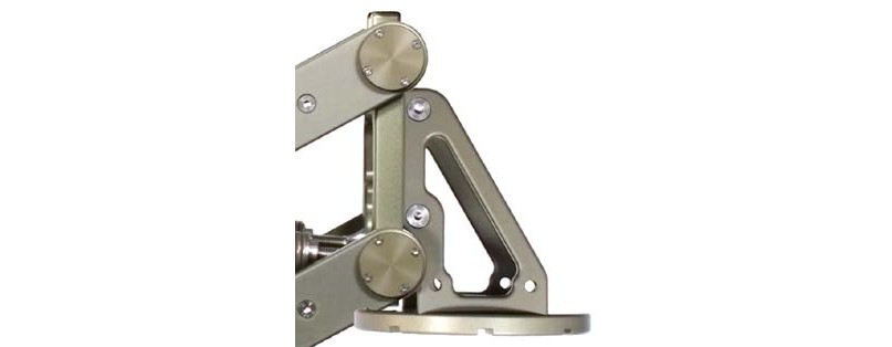
Take out the two locking bolts on each side of the bracket and the two inside locking bolts on the Mitchell plates. Move the bracket into the new position and bolt it together again.
Prepare the shock for the pressure setting
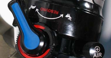
Set the air pressure with everything on: shock absorber, GF-Iso Dampener, head and camera. First turn the red rebound dial fully anti-clockwise and put the blue compression lever on minimum. The shock then moves freely and settles, so you can read the sag properly. Take the cap off the valve and connect a high-pressure shock pump.
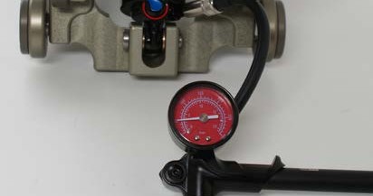
Set the air pressure
The air pressure sets how firm the spring is, and with it the sag. Payload and surface decide the right value. These starting values are a guide, not a rule: 40 kg 0.75 bar (11 psi) · 45 kg 0.86 bar (12.6 psi) · 50 kg 0.96 bar (14 psi) · 55 kg 1.05 bar (15.4 psi) · 60 kg 1.15 bar (16.7 psi) · 65 kg 1.25 bar (18.1 psi).
Rebound damping: red dial
The red dial sets how fast the suspension extends again after a bump. Rebound damping reduces the pogo effect of a shock that bounces back too quickly after a bump.
Compression gate: blue lever
The blue lever sets the slow compression damping. On minimum the gate is open and the suspension is at its softest, which works best on rough ground. We recommend leaving both the dial and the lever fully anti-clockwise, so the valves stay open.
Fine-tune with the springs
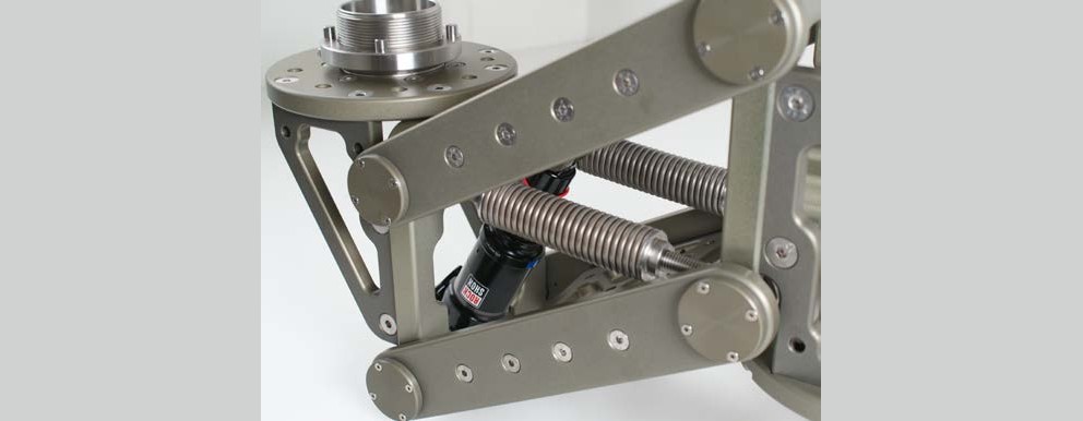
The two tension springs give extra support and finer tuning. Adjust both by the same amount. Seen from the rear of the shock absorber, turning a spring clockwise increases its tension.
Ready for use
Pressure, damping and spring tension are set. The shock absorber is ready to run.
GFM-TM-003 · Rev 2026-11 · Technical changes reserved.